
Have you ever thought of getting your A2000 up and running again but were hesitating to place the old bulky Commodore 1084S monitor back onto your desk. This is the solution for you.
Principle of Operation
I wanted to connect my regular LCD monitor to the Amiga. Unfortunately the Amiga provides a PAL/NTSC resolution image at the Video output port, while the PC monitor requires at least a horizontal frequency of around 30 kHz.
The Amiga community solved this problem by introducing the scandoubler / flickerfixer: The video image is stored to some RAM and sent to a VGA connector at double scan rate.
Sounds simple and is especially simple on the A2000 as this model has an extra video slot for connecting video hardware. This slot has the digital video signals available which are generated by Denise. So there is no need to digitize the analog RGB signals at the video connector plus all the timing signals/clocks like HSYNC/VSYNC are available as well. The drawback compared to other solutions like the Indivison scandoubler is, that the board can be used on A2000 devices only.
For a 640x512 image at a color depth of 3x4 bit you need to store 320k x 12bit with a pixel clock of around 7 MHz. So I used two 256k x 16 bit high speed SRAMs as video storage (this turned out to be not overly smart, as I didn't have enough memory to store the horizontal/vertical retrace periods but needed lots of logic to prevent the scandoubler from capturing during these times). The SRAM needs to be a "SM624016" pin compatible device. I used a IS61WV25616BLL-10IL from ISSI, but many compatible devices are available. The RAM needs to be in a pin compatible 44 pin TSOP (Type II) package, need to run at 3,3V and requires a fast access time that can cope with the 28 MHz operating frequency (i.e. 35 ns).
In order to keep things cheap and simple (5V logic, no FPGA loading, ...) I decided to build the required glue logic into a CPLD instead of an FPGA (the second not overly smart move due to the limited logic resources).
The initial design was simple: Run the SRAM at four times the Amiga clock (4x7 MHz=28 MHz). At every second clock cycle (i.e. at the rate of the 14 MHz Amiga pixel clock) write the current pixel from the Amiga to one of the SRAM devices. One SRAM holds the odd columns of the frame, the other stores the even ones. During the other clock cycles, a full 2x12 bit word (i.e. two pixels are read from both SRAMs at the same time) and sent to the VGA output. As a result, we obtain a pixel clock of 28 MHz at the VGA connector.
The required 4x7 MHz clock was generated out of the 7 MHz Amiga (pixel) clock by a x4 clock multiplier device connected to the CPLD.
Unfortunately this design was too simple. In the era of CRT monitors, one was able to tweak the image with some trimmers on the back of the monitor, so that the 640x512 pixel image fitted to the screen. Today LCDs support only dedicated resolutions (like 720x400, 640x480 or 800x600). In lores mode, I decided to go for a 720x400 resolution leaving a good amount of black lines at the bottom, in hires I went for 640x480 lacking the last 32 lines.
Going to a resolution of 800x600 sounds beneficial for lores and hires screens, but most monitors (at least mine) complain about the slow horizontal frequency of 32 kHz and the even lower vertical frequency of less than 50 Hz resulting from the 28 MHz pixel clock. So I stopped my experiments on that topic.
Consequently I had to regenerate the entire timing for the VGA output and the refresh rate became slightly lower than 50/60 Hz (which seems to be OK for most screens).
Second challenge was to detect progressive and interlaced frames. In interlace mode, a 256 lines odd and even frame are sent at a rate of 50/60 Hz building a full picture at a rate of 25 Hz. Odd and even frames can be distinguished by the timing of the very first lines (i.e. 2 or 3 horizontal lines with vertical sync being asserted by the Amiga). In progressive mode the same 256 lines frame is sent at a rate of 50/60 Hz (there are just odd frames).
As the Amiga supports 4096 colors (i.e. 4 bit per color) only, digital to analog conversion doesn't require fancy DA-converters but a cheap R2R ladder. The output can be connected to a high speed video opamp optionally.
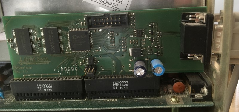
Building the Flickerfixer
The flickerfixer comprises a Xilinx XC95144XL CPLD in a TQFP100 package (which requires some decent SMD soldering skills) plus a clock multiplier to generate the required timing. An optional video opamp (mount resistor package R1, if you don't have a video opamp) and two 256k x 16 SRAMs as video storage and a 3,3V voltage regulator to drive the CPLD.
JTAG Programming
A Xilinx JTAG programmer cable is required to download the CPLD code to the CPLD using the 14 pin pinhead.
WARNING! Be aware that the 14 pin header has a different pinout than the standard XILINX header found on XILINX equipemtn (Platform Cable USB II, Parallel Cable III).
Clock Multiplication
The 28 MHz clock is generated by a clock multiplier in SO-8 packaging. You can use a Pericom PI6C4511 (obsolete) or PT7C4511WE (pin compatible repalcement) or Reneas ICS502.
Don't forget to set the jumpers (located close to the clock device), to select the appropriate operation mode. The jumper settings determine the multiplication factor of the clock multiplier.
On the Pericom devices vonnect S0 and S1 to GND to set x4 mode (i.e. connect 3-5 and 4-6 on J4).
On the ICS502 keep the upper jumper pair open and connect S0 to GND (3-5 on J4)
Done.
The crystal oscillator Q1 is not required. It could be populated for overclocking the Amiga.
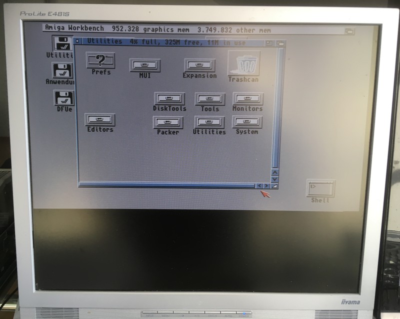
The result
Absolutely stunning, a crystal clear non blurry image ...
How to get it
The full package can be downloaded at Aminet.
http://aminet.net/package/docs/hard/flickerfixer